Relatively simple two-dimensional transport domains can be defined using modified rectangles. Simple rectangular domains are defined by three straight lines, one at the bottom of the domain and two at the sides, while the upper boundary may or may not be straight. Nodes along the upper boundary may in that case have variable x- and z-coordinates, but the lower boundary line must be straight (horizontal or with a specified slope), whereas the left and right boundary lines must be vertical. The flow region can then be discretized into either a structured or an unstructured triangular finite element mesh. The size of the Simple Rectangular Domain is specified in the Rectangular Domain Definition dialog window.
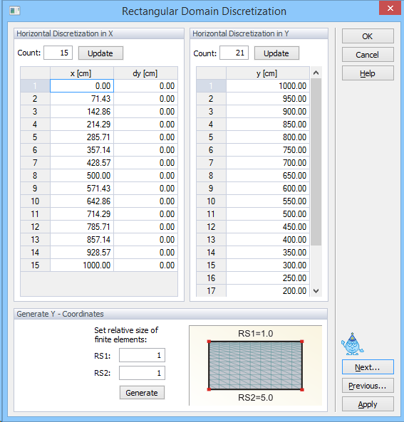
When a structured mesh is used one needs to specify in the Rectangular Domain Discretization dialog window the number of nodes (Count) on the horizontal (Horizontal Discretization in X-Direction) and vertical (Vertical Discretization in Y-Direction) sides of the rectangular region, including their nodal coordinates. The relative size of finite elements on the vertical side can be modified using the RS1 (relative size at the top) and RS2 (relative size at the bottom) factors below General Vertical Coordinates. The element sizes are then proportionally distributed.
The upper boundary is by default parallel with the bottom boundary. Any possible vertical deviations from this parallel line can be defined using dy values (in the Horizontal Discretization in X-Direction part of the window). Relatively general domains can still be defined by properly adjusting the dy values.