On the HYDRUS web side, users can view simple Demos that illustrate the use of the new HYDRUS software, accompanied with brief written explanations of particular commands and actions. We will be continuously expanding this section, offering various Demos and Video Tutorials (http://www.pc-progress.com/en/Default.aspx?h3d-tutorials), based on our own judgment and in response to questions from HYDRUS users.
Below is a description of a single example:
Grid and Work Plane
This demo teaches users how to define Work Planes in the different (x-y, y-z, and x-z) coordinate planes as well as Grid Points (either Cartesian or polar) that both help with graphical input of the transport domain. The demo shows how to define the Origin and the Spacing (in each direction) of grid points and their visibility.
Solid_01
This series of three demos demonstrates how users can create the transport domain shown below. The problem is divided into three parts. First, the main transport domain is defined, then a vertical hole is created in the domain, after which the heights are adjusted.
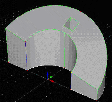
Solid_01_01
In this first demo we start from the very beginning by creating a new project, selecting geometry type, and then creating the following object that has everywhere the same height.
- We first create a New Project Test1.
- In the Geometry Information dialog window we next define the Type of Geometry (3D Layered) and Domain Definition (General).
- Since Work Plane is by default in the x-y coordinate plane, we select the Reverse Z-direction view for this work plane (i.e., the view is from above).
- Next we define two concentric Arcs using three points for each (from the Tools Sidebar). The demo also shows how to move points to a correct location.
- Next we close the domain using two Lines defined by Abscissas (again from the Tools Sidebar).
- We now define Surface by Boundaries. This action instructs the software that the object in the Work Plane represents the bottom of the transport domain (the Base Surface is created). After clicking on the boundary, a dashed line appears inside the object, indicating that the Base Surface was created.
- Next we change the view to Isometric.
- The demo shows different types of manipulations of the Base Surface object, such as scrolling, rotating, and zooming.
- Next we add the third dimension using the command Solid – Extruded (from the Tools Sidebar). One needs to first click at a certain point of the Base Surface and then drag the point to a certain height. This action will create an object that has the same height everywhere (see above).
Solid_01_02
In this demo we will start with the transport domain created in the previous demo and create an opening (hole) in the domain.
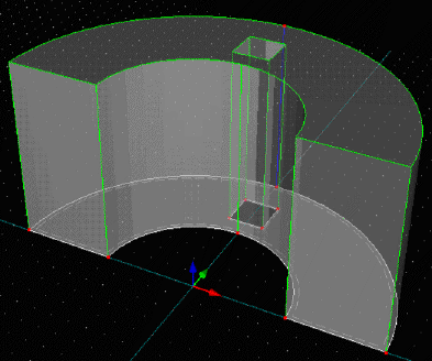
- The demo first shows different views of the transport domain (Full, Transparent, and Wire; Perspective, View All, selected from the toolbar). We again use the command Reverse Z-direction to view the transport domain from above.
- Next, using the command Line – Abscissa, we define the square in the domain. By clicking on the command Opening by Boundaries, we specify that this square extrudes through the entire domain, but is not part of the domain itself (see the picture above).
Solid_01_03
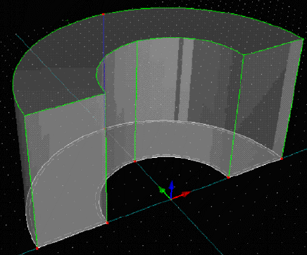
In this demo we will start again with the transport domain created in the previous demo, but no adjust (lower) the height on one side of the transport domain.
- We first select the command Thickness Vector from the Tools Sidebar to adjust the height from 600 cm to 300 cm, and specify this height at two nodes on the right side of the front face of the transport domain.
- Next, we select one point and adjust the height further to 270 cm.
- The demo shows again various types of domain manipulations.