New graphical tools called “Clipper” and "Slicer" obtaining straight cross-sections (planes) throught 3D domains and then displaying data on these planes. For the plane obtained by a Slicer, it is also possible to display a 2D chart on any line located in the plane. The basic Clipping and Slicing features are shown in the video tutorial Clipping and Slicing.
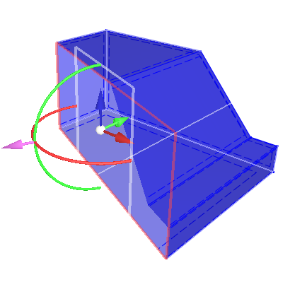
The Clipper and Slicer are controlled by a graphical tool, a manipulator.
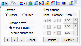
Toolbars icon Clipper contains following command
See also Edit Bar Clipper Tab.
The optimization of GUI for the work with large FE meshes required certain changes in using mesh-sections. Although mesh-sections are still fully supported, the program by default does not generate as many mesh-sections as in Version 2. There is a new graphical tool called a “Clipper” that can be used to cut or slice a 3D mesh. Another new useful function related to mesh-sections is a possibility to select mesh nodes/elements by selecting geometrical objects in the data-explorer tree.
3D Clipping. When working with 3D models, the visible mesh (or geometric objects) can be clipped to view values inside the domain. The clipper is controlled by a graphical tool (a manipulator).
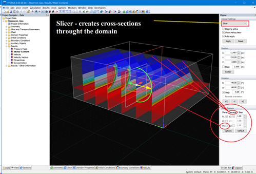
3D Slicing. The Slicer is another tool for a better visualization of 3D models. The number of slices, their position and rotation can be set either in a dialog or graphically.
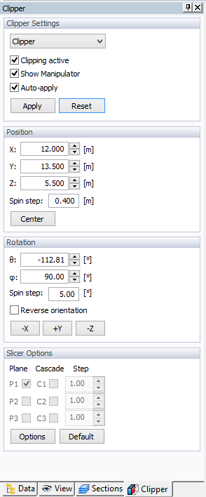
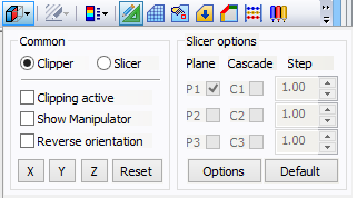
Clipper setting dialog window or pup up dialog in tool bars.
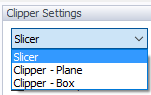
Slicer Drop down Box contains three different settings:
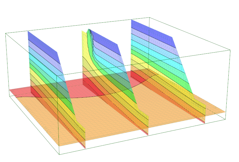
An example of the Slicer tool with 6 vertical and one horizontal cross-sectinal planes.
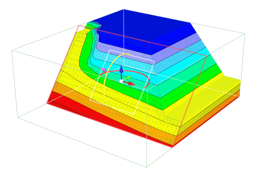
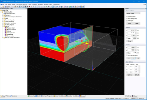
An example of the Clipper Plane tool with a displayed manipulator (defining the position and rotation of a display plane).
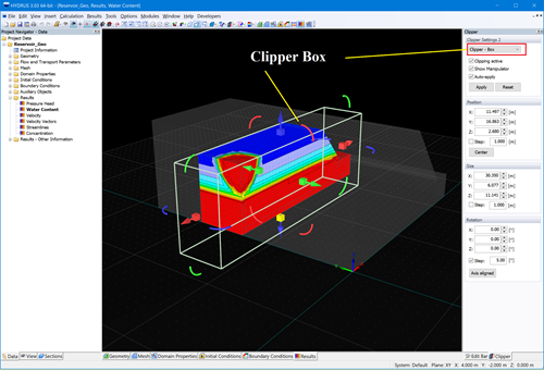
An example of the Clipper Box tool with a displayed manipulator (defining the position and rotation of the box).
Back to Toolbars.