Objects FE-Mesh Refinement define a local density of the FE-Mesh in the vicinity of a particular object. Possible types of FE-Mesh Refinement are:
• FE-Mesh Refinement at point
• FE-Mesh Refinement on Curve given by number of points
• FE-Mesh Refinement on Curve given by FE size
• FE-Mesh Refinement on Surface
• FE-Mesh Refinement on Solid
The Finite Element Mesh Refinement process is carried out in two steps:
1. FE-Mesh Refinement for the 2D-General and 3D-Layered geometries.
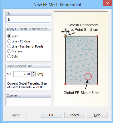
a. When the FE-Mesh Refinement is assigned to a Point (see figure below), users only need to define the finite element size that is to be used at a given point. This FE-size will be used around a given point, while sizes of neighboring FE will be gradually increased until the Targeted FE Size is reached further away in the computational domain. Notice that the dialog window also displays the Global Targeted FE Size. The same FE-Mesh Refinement, i.e., the same refined FE-size, can be assigned to multiple Points in the transport domain.
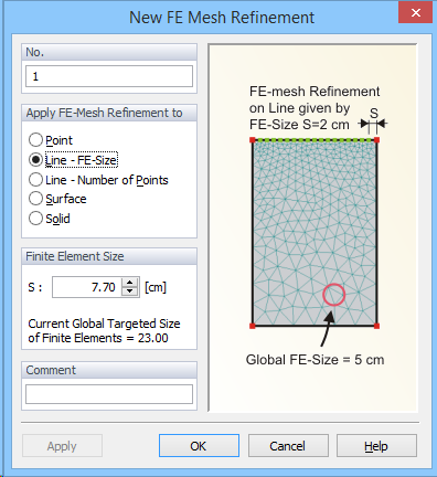
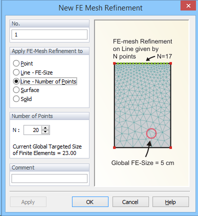
b. There are two ways how the FE-Mesh Refinement can be assigned to a Line. Users can either specify the FE-Size (Line – FE-Size; the first figure below) or the Number of Points (Line – Number of Points; the second figure below) to be used on the entire line. Similarly as for points, the FE-Size (either given directly or calculated from the number of points) will be used on the Line, while sizes of FE away from the Line will gradually increased until the Targeted FE Size is reached further away in the computational domain. Again, the same FE-Mesh Line Refinement, i.e., the same refined FE size, can be assigned to multiple Lines in the computational domain.
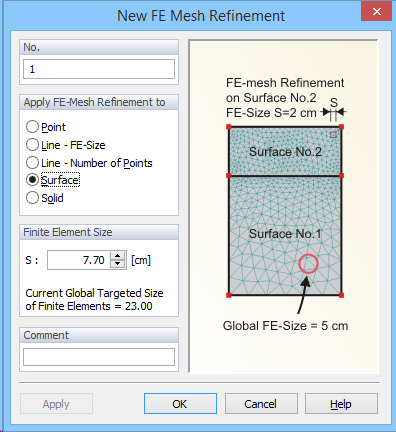
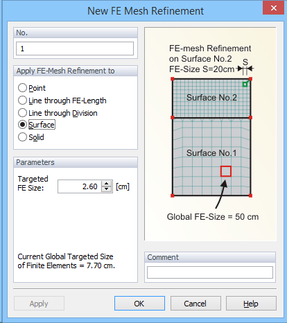
c. The FE-Mesh Refinement can also be assigned to a selected Surface (see figure below). In this case, users need to define FE-Size for a selected Surface. Note that this option is useful only when multiple Surfaces are used in the computational domain. The refined FE-Size is then used on the entire surface, including boundaries with other Surfaces, and the Targeted FE Size is reached only further away in the other Surfaces of the computational domain.
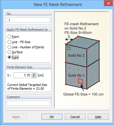
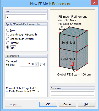
d. The FE-Mesh Refinement can also be assigned to a selected Solid (see figure below). In this case, users need to define FE-Size for a selected Solid. Note that this option is useful only when multiple Solid are used in the computational domain. The refined FE-Size is then used on the entire surface, including boundaries with other Solid, and the Targeted FE Size is reached only further away in the other Solid of the computational domain.
The Point or Surface with an assigned FE-Mesh Refinement are indicated using the following marks: ![]() and
and ![]() ,respectively. FE-Mesh Refinement is marked on curves using green points. visible in the edit mode site. Contrary to other green points on the curves, they can be selected.
,respectively. FE-Mesh Refinement is marked on curves using green points. visible in the edit mode site. Contrary to other green points on the curves, they can be selected.
2. FE-Mesh Refinement for the 3D-General geometries.
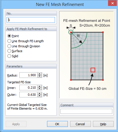
a. There are two ways how the FE-Mesh Refinement can be assigned to a Point. Users can use either Circular or Rectangular refinement. For a Circular Refinement around a point, a radial refinement area is defined around a node in all directions. Users need to specify the Radius of the refinement area, the Inner Targeted FE-Size (i.e., a FE-size immediately around a point), and the Outer Targeted FE-Size (i.e., a FE-size at the outer end of the radial refinement area). The Outer Targeted FE-Size should be equal or slightly smaller than the Global Targeted FE-Size. When generating the FE mesh, the mesh refinement is carried out gradually towards the center because the FE length at the periphery of the refinement area is usually identical with the global mesh width. For larger differences between the inner and outer FE length, it is recommended to set the radius not too small in order to avoid acute-angled triangular finite elements in the refinement area. For a Rectangular Refinement, a rectangular refinement area is defined around a node in all directions. Users need to specify the Side Length of the refinement area and the Inner Targeted FE-Size (i.e., a FE-size immediately around a point).
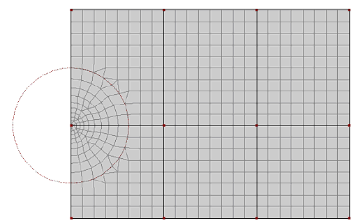
Circular refinements around a node.
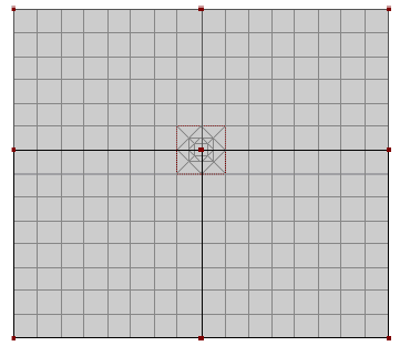
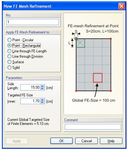
Rectangular refinements around a node.
b. FE-Mesh Refinements assigned to a Line are handled in Genex/T3D similarly as in MeshGen2D. One can again define either the size (spacing; Line through FE-Length) or the number (a specific number of equidistant sub-divisions; Line through Division) of finite elements along a line. In the former case one needs to define the Target FE Length, in the latter case the Number of Division FE Nodes. However, while in MeshGen2D there was a gradual increase in sizes of finite elements away from the Line, in Genex/T3D the refinement affects only one row of finite elements.
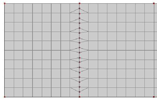
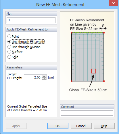
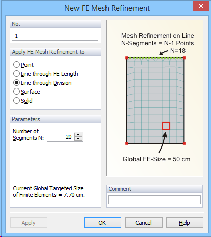
Refinement on a line (by defining either the size or the number of finite elements along a line).
c. It is also possible to define Fe-Mesh Refinements for Surfaces or Solids. In both cases, users need to specify the Targeted FE-Size, which will be set as target size of the finite elements for the entire surface or solid.
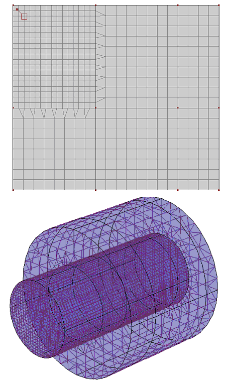
Refinements on a surface (up) or solid (down).
See also Notes on Spatial and Temporal Discretization.