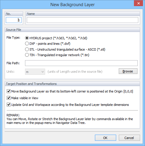
A Background Layer are geometrical objects that can serve as a template for defining the transport domain. A Background Layer consists of nodes and curves that are not part of the transport domain, but its components can be used to define the transport domain. A Background Layer is usually read from the DXF file (AutoCAD), but may be also read from another HYDRUS project (h3d or h3d2), or from STL (stereolithography), TIN (Triangular Irregular Network), or BMT (bitmap) formats.

The project may have at the same time multiple Background Layers (virtually any number) and their visibility can be turned on and off using the View Tab at the Navigator Bar (Auxiliary Objects->Background Layers). Background Layers are displayed in the View window using suppressed (less intense) colors, so that they do not visually disturb when objects of the geometry are being defined. The intensity of display and other parameters can be set (intensity of their display can be set between 0 and 1) in the Display Options dialog window (the Menu command Options->Display Options->Edit). If the location of the template (background layer) is not satisfactory, it can be Moved, Rotated, Mirrored, Stretched , and/or Skewed, as needed.
STL is a file format native to the stereolithography CAD software created by 3D Systems. This file format is supported by many other software packages; it is widely used for rapid prototyping and computer-aided manufacturing. STL files describe only the surface geometry of a three dimensional object without any representation of color, texture or other common CAD model attributes. The STL format specifies both ASCII and binary representations. Binary files are more common, since they are more compact. An STL file describes a raw unstructured triangulated surface by the unit normal and vertices of the triangles using a three-dimensional Cartesian coordinate system. The STL file specifications are at: http://en.wikipedia.org/wiki/STL_(file_format).
TIN files are used for storing triangulated irregular networks using a simple set of xyz coordinates. The TIN file specifications are at:
http://www.xmswiki.com/wiki/TIN_Files
AutoCAD DXF (Drawing Interchange Format, or Drawing Exchange Format) is a CAD data file format developed by Autodesk for enabling data interoperability between AutoCAD and other programs. The data format of a DXF is called a "tagged data" format which "means that each data element in the file is preceded by an integer number that is called a group code. A group code's value indicates what type of data element follows. This value also indicates the meaning of a data element for a given object (or record) type. Virtually all user-specified information in a drawing file can be represented in DXF format.