Inserts a polyline defining a boundary of the transport domain (geometry) graphically using the mouse.
Lines and Polylines are the most commonly used objects for describing the boundaries of a two-dimensional domain and its internal curves. Similarly as for Points, Lines and Polylines can be entered either graphically using the cursor (most common) or using the New Line dialog window (identical to the General Tab of the Edit Line dialog). When entering a new line graphically, users can select the command Insert->Domain Geometry->Line->Graphically from the menu, or Line - Abscissa or Line - Polyline from the Insert Object part of the Domain Geometry version of the Tool Bar at the right side of the View Window, and then enter the lines using the cursor.
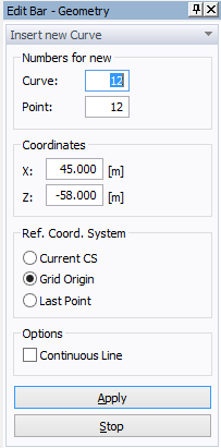
Once a command for defining a new polyline is selected, a cursor in the View Window will become a cross with a small empty circle in the middle. The coordinates of the location of the cursor will be displayed next to the cursor and on the Edit Bar, which will automatically change to the one displayed below. The Edit Bar will also show, which point and curve (their numbers) are being defined and what reference coordinate system (the current coordinate system, the grid origin, or the last inserted point) is used. This command differs from the "Insert Line Graphically" command only by numbering the entire polyline as a single curve, while each abscissa was considered to be a single curve for the latter command. The process of defining a new polyline is ended by pressing the Esc keyboard button, the right mouse button (see the Help part of the Edit Bar), or clicking the Stop button on the Edit Bar.
See also Common Information for Graphical Input of Objects.