Inserts a Thickness Vector graphically.
The term Thickness Vector is used for a vector (usually but not always perpendicular to the Base Surface) that extends the Base Surface to form a solid (the three-dimensional computational domain). The Thickness Vector (i.e., its Boundary Points) is defined and can be edited in the Edit Thickness dialog window.
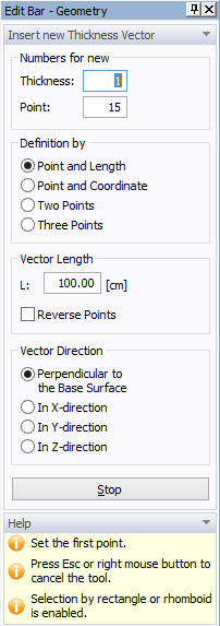
There are several ways in which a Thickness Vector can be specified graphically and these are displayed at the Edit Bar (Displayed below), which appears once a command for defining a Thickness Vector is selected.
- Point and Length: A user specifies the length of the Thickness Vector on the Edit Bar (Vector Length) and with the mouse selects the point to which the Thickness vector is assigned.
- Point and Coordinate: A user specifies the End Coordinate of the Thickness Vector on the Edit Bar (End Coordinate) and with the mouse selects the point to which the Thickness vector is assigned. This method is suitable especially in case, when points located at the upper surface of the domain already exist (see Tutorial 2.07). In this case we need to specify Thickness Vectors whose upper points were read in from a GIS file and we need to create the lower (beginning) points that would be located in the plane of the Base Surface. Note (in the Tutorial) that the Reverse Points option was automatically checked on the Edit Bar. This is because the thickness Vectors have to originate from the Base Surface and not from the upper surface. If the Reverse Points option was not checked, Thickness Vectors would originate from the upper surface and end at the Base Surface.
- Two Points: A user selects graphically two existing Points to form the Thickness Vector. In this case an anchoring (beginning) point of a Thickness Vector is the first selected point. It is therefore important to select points defining a Thickness Vector in the right order, i.e., to first select a point at the Base Surface and only then a point at the upper surface of the domain.
- Three Points: A Thickness Vector is in general defined by three points: an Anchoring Point, a Beginning Point, and an End Point. The Anchoring Point must be located in the Base Surface. The Anchoring Point is usually the same as the Beginning Point (i.e., both Point indices are the same) and one does not have to pay attention to it. However, in general, the Anchoring Point can be different than the Beginning Point, which leads to the so called "offset". This option allows to define Domains that have both upper and lower surfaces deformed, i.e., not a plane.
Vector Direction can be specified to be a) Perpendicular to the Base Surface, b) in X-direction, c) in Y-direction, or d) in Z-direction.
Thickness Vectors can be defined by:
- clicking on individual Points
- selecting points with a rectangle (rhomboid, circle, polygon)
- clicking on a curve – Thickness Vectors will be added to all points of a curve.
Note: Three Thickness Vector needs to be specified to define a Domain with a linearly changing thickness. As long as only two Thickness Vectors are specified, the thickness of the Domain is constant and defined using the first Thickness Vector (with lower index) (since three points are needed to define a plane).