As an alternative to a) “Meshlines,” which need to be defined along edges of finite elements (and thus are broken lines) before calculations are carried out, and b) “Cross-Sections,” which are straight lines through the transport domain (independent of finite elements) that can be defined after calculations are done, Hydrus also provides an option to specify c) “Line Probes,” which are broken lines defined anywhere in the transport domain (also possibly independent of finite elements) and which can be specified after calculations are done.
When presenting simulation results, HYDRUS displays these “Line Probes” and values of a particular displayed quantity (e.g., water contents or concentrations) along these lines. HYDRUS can display graphs of a particular quantity along a Line Probe for a particular Print Time or for all Print Times. When Points defining a Line Probe are not located directly on FE nodes, the quantity values are linearly interpolated from the values in FE nodes.
Edit commands for Line Probes:
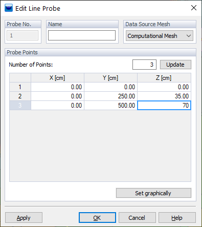
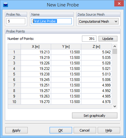
A Line Probe can also be inserted using the Line Probe command, available on the Insert Menu. One can create a set of definition points for the new Line Probe either a) numerically using a table in the New Line Probe dialog window, or b) graphically after clicking on the button “Set Graphically.” When defining a Line Probe numerically, one must predefine the number of definition points (Number of Points) and click on the Update button to update the table before entering definition points coordinates
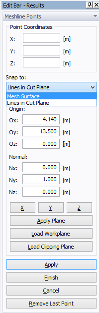
The Graph Polyline Probe function (on the “Edit bar – Results” tab, in the section “Tools and Options”) enables you to define a line in the transport domain or in the slicer plane and, thus, create a sectional diagram of the results along the line.
To display a line chart, use a) the Graphs -> Polyline Probe command which is available on the Results menu, or b) double-clicking on a Line Probe. When the line is activated, you can select the relevant points of the line (or polyline) by mouse-clicks. The coordinates of the points are displayed in the panel, which has a specific layout for this purpose. Here, you can also modify the Snap object, if necessary.
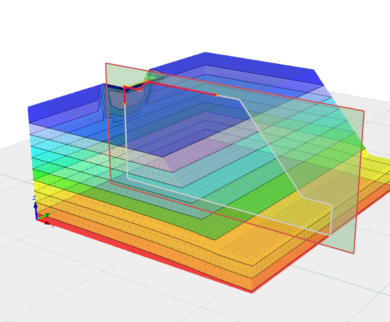
After you select the two (or more) points of the line, click the Finish button.

The Line Probes can be grouped into multiple named groups. The initial set of Line Probes is denominated 0 - Temporary. To save it permanently, use the Save Probe Copy button on the Edit Bar below the list of point probes. A new dialog box is opened where you can define the Name of the Group of Probe Points and check the coordinates of each point.
The current Line Probe is not denominated yet. To save it permanently, use the
Save button. A new dialog box opens, and one can enter the name of the Line Probe and click on OK.
All saved Line Probes are shown on the Navigator Bar under the Auxiliary Objects, where can select various Edit commands, for example, Delete All Line Probes.
See also “Point Probes.”