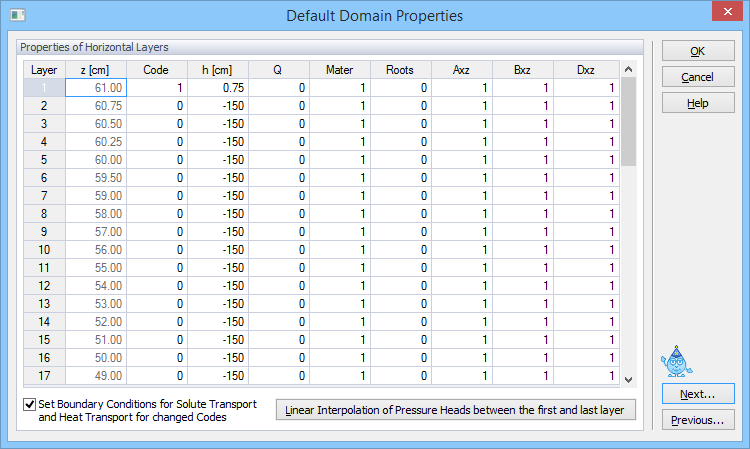
For rectangular two-dimensional domains and for layered three-dimensional domains, immediately after the finite element mesh is generated, one can specify the initial Default Domain Properties in this dialog window. Values listed in this window are initially assigned to each horizontal layer of the transport domain, but can later be modified graphically. The following variables are involved:
Code |
Code of the boundary condition (0 for no flow, -1 for constant flux, +1 for constant head, -2 for unsaturated seepage face, +2 for saturated seepage face, -3 (-7, -8, -9) for variable flux, +3 (+7, +8, +9) for variable head, -4 for atmospheric, - 5 for tile drain, -6 for free drainage) |
h |
Initial value of the pressure head [L]. The initial pressure head changes linearly between the first and last layer if one clicks on the command at the bottom of the dialog (Linear interpolation of pressure heads between the first and last layer). |
Q |
Recharge flux, [L2T-1] and [L3T-1] for 2D and 3D applications, respectively |
Mater |
Material number |
Roots |
Root distribution |
Axz |
Scaling factor for the pressure head |
Bxz |
Scaling factor for the hydraulic conductivity |
Dxz |
Scaling factor for the water content |
Temp |
Initial temperature [K] |
Conc |
Initial concentration (of the equilibrium phase) [ML-3] |
Sorb |
Initial concentration of the nonequilibrium phase (kinetically sorbed [MM-1] or of the immobile region [ML-3]) |
Sol# |
Unsatchem Module: Solution composition number [-] to be used for the initial condition |
Ads# |
Unsatchem Module: Composition number for cation exchange sites [-] to be used for the initial condition |
Prec# |
Unsatchem Module: Composition number for solid phases [-] to be used for the initial condition |
CO2 |
Unsatchem Module: Initial CO2 concentration. |
Values from each line are assigned to the entire layer within the FE-Mesh with the exception of Code (the boundary condition code), which is assigned only to boundary nodes. When multiple values are encountered within the single layer when initiating the table, the cell is left empty instead of displaying any particular value. Unless changed, this variable will not be assigned in a particular layer (after closing the dialog with OK) and original values will remain unchanged.
MS Excel Import/Export: These three commands (Copy Sel., Copy All, and Paste) facilitate the transfer of data from this HYDRUS dialog window to the Excel (or other) spreadsheet.
Set Boundary Conditions for Solute Transport and Heat Transport for changed Codes: This command will lead to assigning Cauchy boundary conditions for solute and heat transport to nodes where the Code was changed.
Do not edit the first two columns (i.e., Layer and z [cm])
See also the "How to Edit Domain Properties" topic.
Additional information about other Domain Properties.