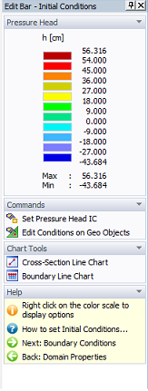
The Edit Bar for Initial Conditions and Pressure Head - h displays a color spectrum that is used to specify the initial conditions, and lists the minimum and maximum values that are imposed on the entire domain. This Edit Bar also includes:
- Edit Commands: Set Values and Values by Pointer. When nodes for which the initial conditions are to be specified are already selected, then the Set Values command calls the Water Flow Initial Condition dialog. When no nodes are selected, then clicking on the Set Values command causes a square cursor to appear, which may be used to select particular nodes, after which the Water Flow Initial Condition dialog window appears. The command Values by Pointer again displays the initial pressure head of the node closest to the cursor.
- Two Chart Tools commands: The Cross-Section Chart and the Boundary-Line Chart. The Cross-Section Chart command allows users to display a particular variable between any two points of the transport domain. The Boundary-Line Chart command allows users to display a particular variable between any two points on the boundary of the transport domain, or along any line that is drawn along edges of finite elements within the transport domain. This line hence does not have to be straight, but can turn in any direction along finite element edges.
- The Help command.