Geo-Sections
Selected Geo-Sections and/or FE-Mesh Sections can be generated using the command Generate Sections in this dialog window obtained using the menu command Edit->Sections->Generate Sections. Geo-Sections can be generated either only for Solids or also for (Boundary and/or internal) Surfaces. Since working with Geo-Sections can be rather tedious when the number of Surfaces exceeds a certain limit, users can select this limit. The default setting (Program Default) is to generate Geo-Sections for up to 50 Surfaces. Note that the number of Surfaces can be prohibitively large for certain 3D-Layered Domains with multiple internal lines and/or layers. Users can therefore choose to generate FE-Mesh Section only for Boundary Surfaces, which are useful when specifying the boundary conditions, and not for internal Surfaces. User can change the default setting (Program Default), save it using the button Save as Default, and then recall it using the button Set Default. Note that different default setting can be saved for different types of domains.
FE-Mesh Section
Different FE-Mesh Sections are generated depending on the type of Domain. For the 3D-Layered Domains, FE-Mesh Sections can be generated for the Boundary Shell, for each Mesh Layer, and for both automatically Generated and User-Defined Geo-Sections. For the 3D-General Domains, FE-Mesh Sections can be generated for the Boundary Shell, and, again, for either automatically Generated or User-Defined Geo-Sections.
Sections serve to divide complex objects (models) into simpler parts. Only the simpler parts are then displayed in the View window while the remaining parts are hidden. Two types of sections exists: those for geometric objects (Geo Sections) and those for the FE-Mesh (FE-Mesh Sections). New sections for both types can be created and named, a list of which is displayed on the Section Tab of the Navigator Bar. Clicking on the Section of the Navigator Bar causes the Section to be displayed in the View window. Multiple Sections can be displayed simultaneously by holding the “Shift” button during the selection. Undesired (to be displayed) parts can be cut off and hidden from the View window using the Cut with Rectangle command. This leads to a temporary section that is remembered by the program and renewed after the project is closed and reopened. New sections can be named and listed in the Navigator Bar by using commands to create new sections. The simplest menu command is the New Section from the View command (alternatively, one can use the Create New Section from Current View command from the Edit Menu of the Sections Tab of the Navigator Bar), which creates a newly named section from currently displayed objects in the View window. The New Section from Selection menu command (alternatively, one can use the Create New Section from Selected Objects command from the Edit Menu of the Sections Tab of the Navigator Bar) creates a newly named section from currently selected objects or the FE-Mesh. The Display Whole Domain (View All) and Display Whole FE-mesh commands causes the entire computational domain or FE-Mesh to be displayed.
Geometric Sections can be created manually (as described above) or automatically. The automatically generated Geo Sections are generated as follows. An object above each part of the Base Surface (in the 3D-Layered Domain) forms a Column, which is divided into Layers, depending on how many vertical layers the domain is divided into. Each such Layer of each such Column then forms one Object (a Domain Section). When we have N Columns (that is, N parts in the Base Surface) and the domain is divided into M horizontal Layers, then the number of generated objects is N*M. At the same time, Surfaces belonging to each of these objects are also generated. Some of these Surfaces are Horizontal and some are Vertical (although these terms are only approximate). Surfaces can then be used to specify Boundary Conditions.
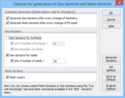
Options for Generation of Geo-Sections and FE-Mesh Sections dialog window.
Selected Geo-Sections and/or FE-Mesh Sections can be generated using the command Generate Sections in this dialog window obtained using the menu command Edit->Sections->Generate Sections. Geo-Sections can be generated either only for Solids or also for (Boundary and/or internal) Surfaces. Since working with Geo-Sections can be rather tedious when the number of Surfaces exceeds a certain limit, users can select this limit. The default setting (Program Default) is to generate Geo-Sections for up to 50 Surfaces. Note that the number of Surfaces can be prohibitively large for certain 3D-Layered Domains with multiple internal lines and/or layers. Users can therefore choose to generate FE-Mesh Section only for Boundary Surfaces, which are useful when specifying the boundary conditions, and not for internal Surfaces. User can change the default setting (Program Default), save it using the button Save as Default, and then recall it using the button Set Default. Note that different default setting can be saved for different types of domains.
Different FE-Mesh Sections are generated depending on the type of Domain. For the 3D-Layered Domains, FE-Mesh Sections can be generated for the Boundary Shell, for each Mesh Layer, and for both automatically Generated and User-Defined Geo-Sections. For the 3D-General Domains, FE-Mesh Sections can be generated for the Boundary Shell, and, again, for both automatically Generated and User-Defined Geo-Sections.
The Section View is the status of the display (in the View window) when only part of the transport domain is displayed (i.e., only one or few, but not all, Sections are displayed). The parts that are not displayed are still visible in the background (gray thin lines and/or surfaces), but are inactive and cannot be selected for various operations. The Section View can be canceled (and the entire domain displayed) using the menu command Section View or the popup menu command Display Whole Domain.