Sections serve do divide complex objects (models) into simpler parts. Only the simpler parts are then displayed in the View window while the remaining parts are hidden. Two types of sections exists: those for geometric objects (Geo Sections) and those for the FE-Mesh (FE-Mesh Sections) (see also Section 5.7 and Table 3 of the User Manual). New sections for both types can be created and named, a list of which is displayed on the Section Tab of the Navigator Bar. Clicking on the Section of the Navigator Bar causes the Section to be displayed in the View window. Multiple Sections can be displayed simultaneously by holding the “Shift” button during the selection. Undesired (to be displayed) parts can be cut off and hidden from the View window using the Cut Section With Rectangle command. This leads to a temporary section that is remembered by the program and renewed after the project is closed and reopened. New sections can be named and listed in the Navigator Bar by using commands to create new sections. The simplest menu command is the Create New Section From Current View command (alternatively, one can use the Create New Section From Current View command from the Edit Menu of the Sections Tab of the Navigator Bar), which creates a newly named section from currently displayed objects in the View window. The Create New Section From Selection menu command (alternatively, one can use the Create New Section from Selected Objects command from the Edit Menu of the Sections Tab of the Navigator Bar) creates a newly named section from currently selected objects or the FE-Mesh. The Display All Domain (View All) and Display Whole FE-mesh commands causes the entire computational domain or FE-Mesh to be displayed.
Section commands:
Sections |
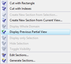
Offers commands to edit Sections: Edit commands: Create New Section From Selection Create New Section From Current View Display commands: |
Automatically Generated Geometrical Sections (Geo-Sections):
While for two-dimensional problems the Geo Sections (displayed at the Navigator Bar at the Section Tab) need to be defined manually, for three-dimensional problems they are generated automatically. An object above each part of the Base Surface forms a Column, which is divided into Layers, depending on how many vertical layers the domain is divided into. Each such Layer of each such Column then forms one Object (a Domain Section). When we have N Columns (that is, N parts in the Base Surface) and the domain is divided into M horizontal Layers, then the number of generated objects is N*M. At the same time, Surfaces belonging to each of these objects are also generated. Some of these Surfaces are Horizontal and some are Vertical (although these terms are only approximate). Surfaces can then be used to specify Boundary Conditions.
For more advanced users:
Vertical Surfaces are always created over the entire curve, which forms the boundary of the Base Surface. When the boundary of the Base Surface consists of several curves, then an independent Vertical Surface is created above each curve. Since the curves of the Base Surface can be arbitrarily divided, Vertical Surfaces can be created relatively freely.
One can use this menu for the following commands:
Return to Edit Menu.