This solid is defined by a Base Surface, which is a 2D domain of an arbitrary shape, and a set of Thickness Vectors, that define the variable thickness of the 3D domain. This is the only solid that defines the entire 3D-Layered Solids. Although such domains can not be fully general, they allow definition of a majority of realistic 3D problems.
1. Base Surface
A Base Surface is formed by one or multiple planar surfaces of arbitrary shape. The base surface can contain openings, internal curves , and internal points (Fig. 1)
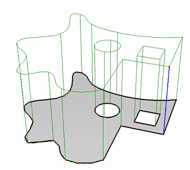
Figure 1. A solid showing the base surface.
If the solid needs to be divided into vertical columns, then these columns must be defined using internal curves in the base surface. The FE-mesh then follows exactly the specified shape of these internal curves (Fig. 2):
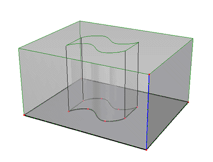
Figure 2. Solid showing separate vertical columns.
2. Thickness Vectors
The height of a solid is defined using one or more Thickness Vectors. Each thickness vector is defined by an Anchor Point P and two Boundary Points N1 and N2. The anchor point P must be part of the base surface, i.e., it must be either a defining point of the external boundary or the internal curve, or an internal point in the base surface. Boundary points N1 and N2 are arbitrary points in 3D space. Coordinates of these points can be edited, thus allowing one to specify the thickness vector in an arbitrary direction (i.e., not necessarily perpendicular to the base surface). Usually the anchor point P is the same as boundary point N1 so that one can use the same index for both P and N1. If, for whatever reason, we do not want to have the base surface on the bottom of the transport domain (Solid) (e.g., when the bottom of the transport domain is not in the same plane), users can make the N1 node be different from P (the red part in Fig. 3).
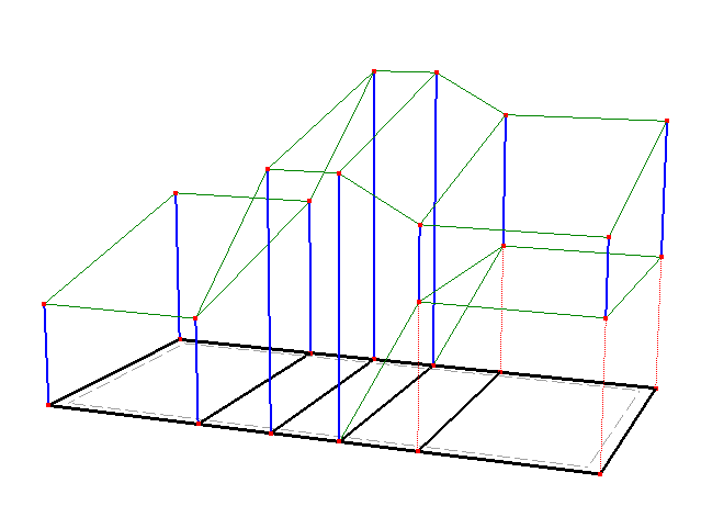
Figure 3. A solid with several thickness vectors.
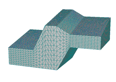
Figure 4. FE-Mesh for the solid in Figure 3.
A list of Thickness Vectors can be defined manually or it can be detected automatically (the "Autodetect" check-box).
3. Calculation of the Top Surface
The height of a solid is constant when less than three thickness vectors are used. Three thickness vectors define a linear plane (with generally an inclined surface). More than three thickness vectors with different lengths then define the top surface that is formed by triangles, whose coordinates are calculated from the thickness vectors using linear interpolation or extrapolation.
AutoSolid must have at least one Thickness Vector or its thickness is not defined. The table below lists the dependence of the shape/thickness of the Solid on the number of defined Thickness Vectors:
Number of Thickness Vectors |
Thickness of the 3D-Layered Solid |
N = 0 |
Not defined |
N > 0, N < 3 |
Constant |
N = 3 |
Linear |
N > 3 |
Variable. Piecewise linear |
When breaks in the slope of the top surface are to be defined exactly, then it is necessary to define internal curves in the base surface. Figures 5 and 6 show the importance of having internal curves (or not having them) in the Y direction for proper definition of the solid (compare Figures 3 and 5 Figures 4 and 6).
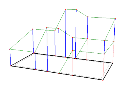
Figure 5. Missing internal curves in the base surface.
Figure 6. Consequence of missing an internal curve in the base surface on the FE-Mesh of the top surface.
4. Base Surface in Other than the Horizontal Plane
A base surface can be defined by a plane other than the horizontal plane, while thickness vectors can be defined in other than the vertical direction. Figures 7 and 8 show an example of a solid that has a base surface in the XZ plane and thickness vectors in the Y direction.
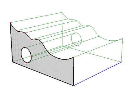
Figure 7. A solid with its base surface in the XZ plane and thickness vectors in the Y direction
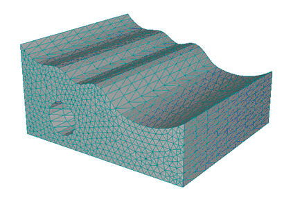
Figure 8. FE-Mesh for a solid with its base surface in the XZ plane and thickness vectors in the Y direction
5. Division of a Solid into Columns
Notice that the Base Surface must be defined using several Surfaces (see Figure 1). Parts of the Solid above each Surface are called Columns and serve to geometrically divide the Solid in the vertical direction. All Surfaces defining the Base Surface must lie in a single plane. A list of these Surfaces can be defined manually using indexes or can be Autodetected by the program (the "Autodetect" option). A division of a Solid into Columns leads to an automatic creation of Mesh Sections that correspond with Columns after the generation of the FE-Mesh. These Mesh Sections can be used to define various properties (e.g., materials distribution) or initial and boundary conditions.
6. Division of a Solid into Geo-Layers
Geo-Layers (called Sub-Layers in Version 1 and used alternatively in this text) are used to divide a Solid in the horizontal direction (Figure 9).
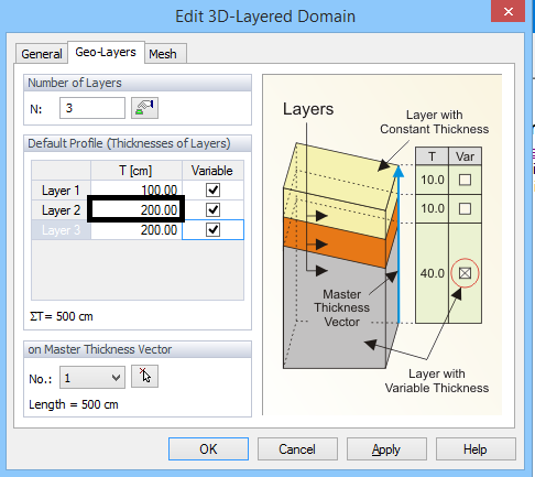
Figure 9. Division of a Solid into Geo-Layers.
It is possible in the Edit Solid dialog to define number of Layers and their Thicknesses. A Solid has always one Master Thickness Vector, which is one of Thickness Vectors of a Solid, that has a special meaning as described below.
A thickness of a Layer is calculated as follows:
7. Individual specification of different Thicknesses of Geo-Layers at different Thickness Vectors.
In the preceding paragraph we have described how to define Thicknesses of Layers on the Master Thickness Vector using a table. This table represents the so called Profile, i.e., a particular distribution of thicknesses. If one wants to define precisely the division of thicknesses also on other vectors than the Master Thickness Vector, then it is necessary to create additional Special Profiles and use then on corresponding Thickness Vectors. Figure 10 shows a dialog for the creation of Special Profiles. There is always a Default Profile, which corresponds to the table described in 6 above. One can create new profiles, change their thicknesses or delete them. One can simultaneously also see a list of Thickness Vectors where the selected Profile is used.
Related Topics
Insert Hexahedral Solid Graphically
Insert 3D-Layered Solid Graphically
Insert 3D-Layered Solid Numerically
Insert 3D-General Solid Graphically
Insert 3D-General Solid Numerically