The FE-Mesh Parameters dialog window has six tabs, i.e., the Main Tab (for two-dimensional and three-dimensional applications), the Stretching Tab, the Meshgen Tab, the Options Tab, the Sections Tab, and the Export Tab.
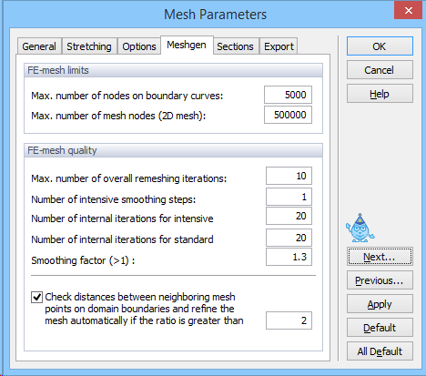
Parameters for the unstructured triangular finite element generator are given in the Meshgen Tab of the FE-Mesh Parameters dialog window. The parameters are divided into FE-Mesh Limits (which limits the number of elements) and FE-Mesh Quality (which affects the smoothness of the FE mesh) groups.
The following parameters are specified in the FE-Mesh Limits group:
Maximum Number of Nodes on Boundary Curves: This is the maximum total number of nodes on all boundary curves for two-dimensional applications, or on all boundary curves defining the bottom plane (base surface) for three-dimensional applications.
Maximum Number of FE-Mesh Nodes (2D Mesh): This is the maximum total number of finite element nodes in two-dimensional domains, or on the bottom plane (base surface) of three-dimensional domains.
Both parameters are mainly informative and may lead to an interruption of the FE-mesh generation process. The mesh generation is interrupted by the message: Achieved the maximum number of nodes! This means that the maximum allowed number of nodes (either on the boundary curves or in the two-dimensional domain) was reached during the mesh generation process. This is usually a consequence of having too many nodes along the boundaries (the number of mesh nodes inside a domain increases approximately with the square of the number of boundary nodes). It is then necessary to decide whether or not so many nodes are needed for the envisioned triangular mesh. If the answer is ‘yes’ then the maximum number of nodes must be increased in this dialog window. If the answer is ‘no’ then it is necessary to decrease the Targeted FE Size or to increase the Smoothing Factor (in the FE-Mesh Quality group discussed below).
The following parameters are specified in the FE-Mesh Quality group:
Maximum Number of Overall Remeshing Iterations:
This number defines the maximum number of iterations during finite element mesh remeshing. In most cases the resulting mesh is obtained within fewer iterations than the default value of 10. In some cases the repeated adding and removing of nodes can cause an infinite loop. In that case (or when the mesh generation process converges very slowly) the code terminates after reaching the maximum number of iterations as defined by this value.
Number of Intensive Smoothing Steps:
Intensive smoothing repeats the operations of Delaunay remeshing and smoothing until there are no more changes during the Delaunay remeshing step. This parameter specifies the number of intensive smoothing cycles in the beginning of the mesh generation process, which can significantly influence the mesh smoothness. However, too many smoothing cycles can significantly slow down the mesh generation process. The recommended value is between 1 (less smoothing) and 3 (more smoothing).
Number of Internal Iterations for Intensive Smoothing:
This number defines the maximum number of iterations during one intensive smoothing step. This number guaranties that intensive smoothing will stop after a specified number of iterations, even when the prescribed criterion is not reached (i.e., some changes would still occurduring Delaunay remeshing).
Number of Internal Iterations for Standard Smoothing:
This number defines the maximum number of iterations while solving the elliptic equations used during mesh smoothing, a process needed during mesh smoothing; it significantly influences the final smoothness of the mesh. A higher number of iterations improves the mesh smoothness. It serves little purpose to increase the number above 20 since the mesh is then virtually constant anyway, while the whole process of mesh generation would be slowed down significantly.
Smoothing Factor:
The smoothing factor is the ratio of the maximum and minimum height of a finite element triangle. For a triangle with equal sizes this factor is equal to 1 (which is theoretically not achievable for finite element meshes). The smoothing factor can be decreased to a value of about 1.1 when a highly smooth finite element mesh is required and, vice-versa, can be increased when a course mesh can be tolerated. The smoothing factor significantly affects the final number of elements.
In general, the default values in the FE-Mesh Parameters dialog window should be preserved; only experienced users should modify the various parameters needed for the mesh generation process.
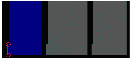
Check distances between neighbouring FE-mesh points: When the option at the bottom of this window is checked, HYDRUS compares distances between the neighboring nodes on the domain boundaries. When the ratio of distances between two neighboring nodes is larger than F, the FE mesh is automatically refined. The graph below shows an example with the option on and off.: When the option at the bottom of this window is checked, HYDRUS compares distances between the neighboring nodes on the domain boundaries. When the ratio of distances between two neighboring nodes is larger than F, the FE mesh is automatically refined. The graph below shows an example with the option on and off.