The FE-Mesh Parameters dialog window has six tabs, i.e., the Main Tab (for two-dimensional and three-dimensional applications), the Stretching Tab, the Meshgen Tab, the Options Tab, the Sections Tab, and the Export Tab.
For 3D-Layered Geometries:
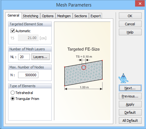
The Targeted FE size (i.e., the average size of the triangular elements in the generated finite element mesh) is specified on the Main Tab. The program selects by default a Targeted FE Size. Users can change this value by deselecting the Automatic check box. The finite element mesh with this Targeted FE size can be further modified using various tools, such as Stretching in different directions (on the Stretching Tab) to make the mesh anisotropic, specifying the Maximum Number of Nodes on Boundary Curve (on the MG-Options Tab,) and Minimum Number of Nodes on Boundary Curve (on the Options Tab), and using Finite Element Mesh Refinement. While the Page Default command sets default values on a particular tab of the FE-Mesh Parameters, the All Default command sets default values on all four tabs.
For three-dimensional applications, a user can specify on the Main Tab the No. of Horizontal Layers, which are layers parallel to the Base Surface to add the third dimension to the problem and if the finite elements used to discretize the three-dimensional domain are to be Tetrahedrals or Triangular Prisms. It is recommended to use Triangular Prisms rather than Tetrahedrals since then the number of finite elements is three times smaller and thus the calculations are faster.
For 3D-General Geometries:
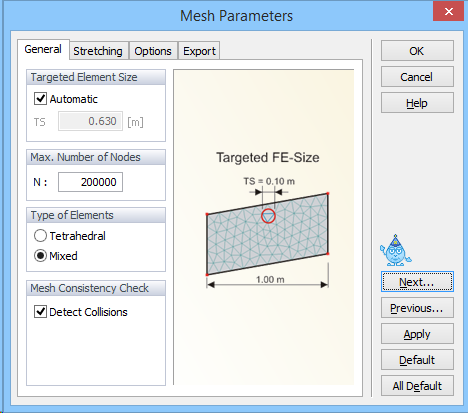
Here the No. of Horizontal Layers is replaced with the Max. Number of Nodes in the FE-Mesh. The three-dimensional transport domain can be discretized using either Tetrahedrals or Mixed Elements. It is recommended to use Mixed Elements rather than Tetrahedrals since then the number of finite elements is much smaller and thus the calculations are faster.
For 3D-General geometries, users also need to specify the Maximum Number of Nodes in the FE mesh. This is the maximum number of finite element nodes in the entire three-dimensional domain. Similarly as in the MG-Options dialog for MeshGen when this is specified for a two-dimensional domain (Fig. 94) when this maximum number is reached a warning will appear Achieved the maximum number of nodes! This means that the maximum allowed number of nodes was reached during the mesh generation process and the user needs to decide whether or not so many nodes are needed for the envisioned FE mesh and either increase this number or adjust other parameters so that less nodes (and FE elements) are generated.
For 3D-General geometries, there is in the Mesh Consistency Check section an additional check box Detect Collisions. This check box is important only for complex 3D-General geometries consisting of multiple solids. When this check box is on, the program checks "collisions" of different objects. The solids cannot intersect each other without having the intersections properly defined using boundary curves. The program also detects if one Solid is entirely inside of another Solid (i.e., its boundaries do not intersect). The former Solid has to be in such case defined as an Opening (Hole, Cavity). The check box Detect Collisions enables users to turn off this check in cases, when they are absolutely sure that there are no such collisions and they still receive warning about a collision of solids.