The FE-Mesh Parameters dialog window has six tabs, i.e., the Main Tab (for two-dimensional and three-dimensional applications), the Stretching Tab, the Meshgen Tab, the Options Tab, the Sections Tab, and the Export Tab.
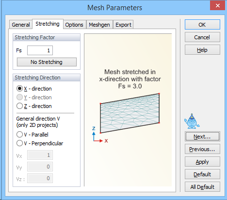
Stretching of the finite element mesh (i.e., the degree of mesh anisotropy in a certain direction) is defined using the Stretching Factor and Stretching Direction. The finite elements are made larger in the particular Stretching Direction if the Stretching Number is larger than one, and smaller if less that one. The result of this transformation is a mesh deformed in the given direction, which can be desirable for problems that, for example, require different spatial steps (mesh sizes) in the X and Y directions. The Stretching Direction is defined by a vector with two coordinates (Vx and Vz) for vertical two-dimensional domains. For three-dimensional problems this vector requires three components (Vx, Vy, and Vz).
More information about Local FE-Mesh Stretching.