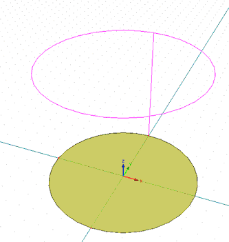
A General Solid can be defined by extruding a Solid from a Surface (one or multiple simultaneously):
Process of Extruding:
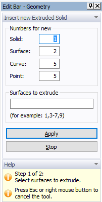
Approach 1: Start a tool and click on a given Surface, which is to be extruded. It is important where a click occurs. The program finds a closest Node on a Surface Boundary and the extruding distance (height) is measured in this node. The extruding height is measured on a line passing through this node.
Approach 2: When you want to extrude multiple surfaces at the same time, you need to press the Left Shift keyboard button before selecting desired Surfaces (you can add or remove Surfaces). After a selection is made, release the Left Shift button and start extruding selected surfaces.
Approach 3: First select desired surfaces and then click the Edit Bar command “Solid – Extruded”. This will start the extruding process for all selected surfaces.
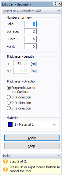
One can extrude in the direction of X, Y, and Z axis or in the direction perpendicular to an extruded Surface. When a Surface is not in a plane (e.g., is curved) and perpendicular extruding is selected, extruding is done in directions of local perpendicular lines to an extruded Surface.
During extruding one can select on the Edit Bar the length step (dL) or enter numerically desired length of extruding (L).
Note that the command Extrude can be used only for Planar, Quad, and B-Spline Surfaces and it cannot be used for Partial Surfaces and for Surfaces containing a zero Curve (i.e., a curve with a zero length from point P to point P).
Related Topics
Insert Hexahedral Solid Graphically
Insert 3D-Layered Solid Graphically
Insert 3D-Layered Solid Numerically