Finite Element Mesh can be stretched in a general direction either globally (the entire transport domain) or locally (at particular Surfaces; parts of the transport domain) using FE-Mesh Stretching. Stretching of the finite element mesh (i.e., the degree of mesh anisotropy in a certain direction) is defined using the Stretching Factor and Stretching Direction. The finite elements are made larger in the particular Stretching Direction if the Stretching Factor Fs is larger than one, and smaller if less that one (i.e., shrinking). The result of this transformation is a mesh deformed in the given direction, which can be desirable for problems that, for example, require different spatial steps (mesh sizes) in the X and Y directions. The Stretching Direction is defined by a vector with two coordinates (Vx and Vz) for vertical two-dimensional domains. For three-dimensional problems this vector requires three components (Vx, Vy, and Vz).
The Global FE-Mesh Stretching is defined using the FE-Mesh Stretching tab of the FE-Mesh Parameters dialog window. The Local FE-Mesh Stretching is defined using the Menu Command "Insert->FE-Mesh->Mesh Stretching - Dialog", the Edit Bar Command "Insert Mesh Stretching", or the Navigator Bar Command "FE-Mesh->FE-Mesh Stretching" and clicking on a particular stretching.
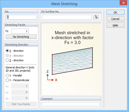
This dialog window (Mesh Stretching) allows users to define "Mesh Stretching" by defining the Stretching Factor Fs and the Stretching Direction, and to assign it to a selected Surface (part of the transport domain) (On Surface No.; this can be assigned numerically or graphically). The Stretching Direction can be defined in the direction of main coordinate axes X, Y, and Z, or using a General Direction Vector V, defined by its coordinates Vx, Vy, and Vz. The Stretching (when Fs>1) or (actually) Shrinking (when Fs<1) can be defined to be either Parallel or Perpendicular to this General Direction Vector V. The General Direction Vector V can be also defined by graphically selecting two points in the transport domain (Pick Two Points).
All local FE-Mesh Stretchings can be deleted using the Edit Bar Command "Delete All Stretchings".
Figure below shows an example of the finite element mesh with three FE-Mesh Stretchings assigned to areas below the domain surface.
